【Cisco】SSHログインマクロ

Cisco機器に対し、SSHログインするTeraTermマクロを作成したので、ご紹介します。
また、複数台の機器に対し、連続でログ取得をするTeraTermマクロについてはこちらを参照のこと。
※今回紹介するマクロを改良すれば、YamahaやJuniper、Alaxalaなど、さまざまなNW機器ベンダ製品にも対応可能です。是非ご参考に。
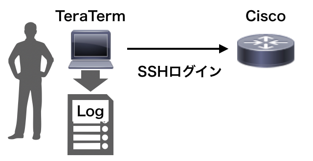
動作としては、

Cisco機器(1台)へSSHログイン→特権モードへ移行→ログ保存開始→terminal length 0を投入

になります。

ぜひご参考に。

01_SSHログイン.ttl

;; SSH接続用Macro

;;;;;;;;;;;;;;;;;;;;;;;;;;;;;;;;
;    ログイン用パラメータ         ;
;;;;;;;;;;;;;;;;;;;;;;;;;;;;;;;;

    hostname = 'RT01'
    username = 'cisco'
    ipaddr = '192.168.1.1'
    sshpasswd = 'cisco'
    enablepasswd = 'cisco'


;;;;;;;;;;;;;;;;;;;;;;;;;;;;;;;;
;    ログ用パラメータ            ;
;;;;;;;;;;;;;;;;;;;;;;;;;;;;;;;;

    portnum = '22'
    logname = '01_SSH_login_'
    logdir = 'log'


;;;;;;;;;;;;;;;;;;;;;;;;;;;;;;;;
;    ログ保存用ディレクトリ作成    ;
;;;;;;;;;;;;;;;;;;;;;;;;;;;;;;;;

    getdir CRNTDIR
    cmd = 'cmd /c mkdir '
    Strconcat cmd '"'
    Strconcat cmd CRNTDIR
    Strconcat cmd '¥'
    Strconcat cmd logdir
    Strconcat cmd '"'
    exec cmd "HIDE"


;;;;;;;;;;;;;;;;;;;;;;;;;;;;;;;;
;    SSHログイン                ;
;;;;;;;;;;;;;;;;;;;;;;;;;;;;;;;;

    msg = ipaddr
    Strconcat msg ':portnum /ssh /auth=password /user='
    Strconcat msg username
    Strconcat msg ' /passwd='
    Strconcat msg sshpasswd
    Strconcat msg inputstr

    Connect msg

    If result <> 2 then
        Strconcat logfile ipaddr
        Strconcat logfile '.error'
        Filecreate ERRORFILE logfile
        Fileclose ERRORFILE
        Closett
        Return
    Endif


;;;;;;;;;;;;;;;;;;;;;;;;;;;;;;;;
;    ログファイル用現在時刻取得   ;
;;;;;;;;;;;;;;;;;;;;;;;;;;;;;;;;

    Getdate Str_Getdate
    Strcopy Str_Getdate 1 4 Str_Year
    Strcopy Str_Getdate 6 2 Str_Mon
    Strcopy Str_Getdate 9 2 Str_Day

    Gettime Str_Gettime
    Strcopy Str_Gettime 1 2 Str_Hour
    Strcopy Str_Gettime 4 2 Str_Min
    Strcopy Str_Gettime 7 2 Str_Sec

    Strconcat nowtime '_'
    Strconcat nowtime Str_Year
    Strconcat nowtime Str_Mon
    Strconcat nowtime Str_Day
    Strconcat nowtime Str_Hour
    Strconcat nowtime Str_Min
    Strconcat nowtime Str_Sec
    Strconcat nowtime '.txt'


;;;;;;;;;;;;;;;;;;;;;;;;;;;;;;;;
;    ログ保存開始               ;
;;;;;;;;;;;;;;;;;;;;;;;;;;;;;;;;

    Strconcat logname hostname
    Strconcat logname nowtime

    getdir FILEPATH
    Strconcat FILEPATH '¥'
    Strconcat FILEPATH logdir
    Changedir FILEPATH

    Strconcat FILEPATH '¥'
    Strconcat FILEPATH logname
    Logopen FILEPATH 1 1

    Logwrite '****************************************'#13#10
    Logwrite 'Hostname: '
    Logwrite hostname
    Logwrite #13#10
    Logwrite 'IP Address: '
    Logwrite ipaddr
    Logwrite #13#10
    Logwrite 'Execution time: '
    Str_Get = Str_Getdate
    Strconcat Str_Get ' '
    Strconcat Str_Get Str_Gettime
    Logwrite Str_Get
    Logwrite #13#10
    Logwrite '****************************************'#13#10
    Logwrite #13#10
    Logwrite #13#10
    Sendln ''


;;;;;;;;;;;;;;;;;;;;;;;;;;;;;;;;
;    [Cisco]特権モードへ移行      ;
;;;;;;;;;;;;;;;;;;;;;;;;;;;;;;;;

    Wait '#' ']$' ']#' '>'
    If result = 4 then
        Sendln 'enable'
        Wait 'assword:'
        Sendln enablepasswd
        Wait '#'
        Sendln 'terminal length 0'
        Wait '#'
    Endif

【Mac】VirtualBoX上のVMをGNS3で使えるようにする方法

MacにおけるGNS3内で、 VirtulBox上のVMを使用できるようにする方法を調べましたので、記載していきます。

準備

あらかじめ、 VirtualBoxをインストールしておきます。なお、VirtualBox自体のインストール方法は割愛します。

VirtualBox側の設定

GNS3で追加したいVMをあらかじめVirtualBox内で作成しておきます。
 [設定] - [ネットワーク]タブ – [ネットワークアダプターを有効化]にチェックを入れます。この時、[割り当て:]を[未割り当て]を選択します。今回は、「CentOS-1」「CentOS-2」の2つを追加していきます。

図:VirtualBox側の設定

GNS3側の設定

先ほど作成したVMをGNS3側で使用できるようにしていきます。

まず、[GNS] → [Preferences]を選択します。

次に、[VirtualBox VMs] → [New]を押下し、[VM list]であらかじめ作成しておいたVMを選択し、Finishを押下します。

これでGNSのテンプレートに先ほど選択したVM名が追加され、他のRT等と同じように扱えるようになります。

L2TP動作確認

最近「L2TP」という技術に触れたので、覚書も含め、動作確認になります。

L2TPとは?

L2TP(Layer 2 Tunneling Protocol)は、L2トンネリングプロトコルの一つで、通信をカプセル化することでVPNを構築することが可能になります。

L2TPを使用すると、物理的に離れた拠点間を同一セグメントとすることができます。例えば、下記のようなインターネットを経由し拠点間を結ぶNW構成においても、L2TPを使用すれば、End-To-Endの通信も同一セグメントとして通信可能となるわけですね。もちろんTracerouteも1Hopで到達可能となるわけです。

「支店の引越しをしたい!でもセグメントは変えたくない!」なんて場合に使えそうですね!

図:L2TPイメージ

検証目的

本検証の目的を以下に記載します。

  • 複数セグメントを経由するL2TPトンネルを構築すること
  • L2TPv3を使用すること
  • L2TPv3パケットの送信元I/FはループバックI/Fとすること
  • 各RT間ではOSPFにより経路情報を交換すること

検証構成

本検証における構成図を以下に記載します。

R1-R2間でL2TPトンネルを構築し、EdgeRT1およびEdgeRT2を同一セグメントとする。

検証Config

R1

!
 hostname R1
 !
 pseudowire-class L2TP_Test
  encapsulation l2tpv3
  ip local interface Loopback0
 !
 !
 !
 !
 interface Loopback0
  ip address 1.1.1.1 255.255.255.255
 !
 interface Ethernet0/0
  no ip address
  full-duplex
 !
 interface Ethernet0/0.200
  encapsulation dot1Q 200
  ip address 20.0.0.2 255.255.255.252
 !
 interface Ethernet0/1
  no ip address
  full-duplex
  no cdp enable
 !
 interface Ethernet0/1.100
  encapsulation dot1Q 100
  no cdp enable
  xconnect 2.2.2.2 1 encapsulation l2tpv3 pw-class L2TP_Test
 !
 router ospf 10
  log-adjacency-changes
  network 1.1.1.1 0.0.0.0 area 0
  network 20.0.0.2 0.0.0.0 area 0
 !
 end

R2

!
 hostname R2
 !
 pseudowire-class L2TP_Test
  encapsulation l2tpv3
  ip local interface Loopback0
 !
 !
 !
 !
 interface Loopback0
  ip address 2.2.2.2 255.255.255.255
 !
 interface Ethernet0/0
  no ip address
  full-duplex
 !
 interface Ethernet0/0.201
  encapsulation dot1Q 201
  ip address 20.1.0.2 255.255.255.252
 !
 interface Ethernet0/1
  no ip address
  full-duplex
  no cdp enable
 !
 interface Ethernet0/1.100
  encapsulation dot1Q 100
  no cdp enable
  xconnect 1.1.1.1 1 encapsulation l2tpv3 pw-class L2TP_Test
 !
 router ospf 10
  log-adjacency-changes
  network 2.2.2.2 0.0.0.0 area 0
  network 20.1.0.2 0.0.0.0 area 0
 !
 end

R3

!
 hostname R3
 !
 !
 !
 !
 interface Ethernet0/0
  no ip address
  full-duplex
 !
 interface Ethernet0/0.200
  encapsulation dot1Q 200
  ip address 20.0.0.1 255.255.255.252
 !
 interface Ethernet0/1
  no ip address
  full-duplex
 !
 interface Ethernet0/1.201
  encapsulation dot1Q 201
  ip address 20.1.0.1 255.255.255.252
 !
 router ospf 10
  log-adjacency-changes
  network 20.0.0.1 0.0.0.0 area 0
  network 20.1.0.1 0.0.0.0 area 0
 !
 end

動作確認

L2TP状態確認

L2TPの状態確認は以下のコマンドで実施します。

  • show xconnect all :XC ST, S1, S2 が UPになっていること
  • show l2tp session :State が est になっていること
  • show xconnect all

※show xconnect allについては、本検証で使用したIOS versionで確認不可のため、割愛

  • show l2tp session

R1#show l2tun session
%No active L2F tunnels
L2TP Session Information Total tunnels 1 sessions 1
LocID RemID TunID Username, Intf/ State Last Chg Uniq ID
Vcid, Circuit
42195 59976 44757 1, Et0/1.100:100 est 00:32:00 3
%No active PPTP tunnels
R1#

R2#show l2tun session
%No active L2F tunnels
L2TP Session Information Total tunnels 1 sessions 1
LocID RemID TunID Username, Intf/ State Last Chg Uniq ID
Vcid, Circuit
59976 42195 52279 1, Et0/1.100:100 est 00:33:41 7
%No active PPTP tunnels
R2#

ARPテーブル確認

EdgeRT1#show interfaces ethernet 0/0 | include address
Hardware is AmdP2, address is cc03.0e21.0000 (bia cc03.0e21.0000)
EdgeRT1#
EdgeRT1#
EdgeRT1#
EdgeRT1#show ip arp
Protocol Address Age (min) Hardware Addr Type Interface
Internet 10.10.10.2 150 cc04.0e22.0000 ARPA Ethernet0/0.100
Internet 10.10.10.1 – cc03.0e21.0000 ARPA Ethernet0/0.100
EdgeRT1#

EdgeRT2#show interfaces ethernet 0/0 | include address
Hardware is AmdP2, address is cc04.0e22.0000 (bia cc04.0e22.0000)
EdgeRT2#
EdgeRT2#
EdgeRT2#
EdgeRT2#sh ip arp
Protocol Address Age (min) Hardware Addr Type Interface
Internet 10.10.10.2 – cc04.0e22.0000 ARPA Ethernet0/0.100
Internet 10.10.10.1 150 cc03.0e21.0000 ARPA Ethernet0/0.100
EdgeRT2#

ARPテーブルに互いのMACアドレスが載っていることがわかります。

通信経路確認

EdgeRT1#traceroute 10.10.10.2
Type escape sequence to abort.
Tracing the route to 10.10.10.2
1 10.10.10.2 120 msec 88 msec 88 msec
EdgeRT1#

EdgeRT2#traceroute 10.10.10.1
Type escape sequence to abort.
Tracing the route to 10.10.10.1
1 10.10.10.1 124 msec 120 msec 92 msec
EdgeRT2#

Tracerouteも1Hopで到達していることがわかります。

MPLS動作確認 -その3

MPLS動作確認 -その1
MPLS動作確認 -その2の続きになります。

検証構成

検証構成図の再掲になります。

検証Config

次は、CE1〜4になります。CEはシンプルにダイナミックルーティングは使用せず、デフォルトルートをPE側へ向けます。
※CE2〜4は割愛します。

CE1

!
 hostname CE1
 !
 !
 ip cef
 no ip domain lookup
 !
 !
 !
 !
 interface Ethernet0/0
  ip address 192.168.11.2 255.255.255.0
  full-duplex
 !
 interface Ethernet0/1
  ip address 10.1.0.1 255.255.255.0
  full-duplex
 !
 ip route 0.0.0.0 0.0.0.0 192.168.11.1
 !
 end

動作確認

通信経路

PC1 → PC2

PC-1> trace 10.2.0.2 -P 1
trace to 10.2.0.2, 8 hops max (ICMP), press Ctrl+C to stop 
1   10.1.0.1   11.507 ms  10.435 ms  10.765 ms 
2   192.168.11.1   35.814 ms  35.878 ms  24.181 ms 
3   192.168.10.1   93.991 ms  82.439 ms  82.754 ms 
4   192.168.21.1   59.543 ms  60.866 ms  58.575 ms 
5   192.168.21.2   67.757 ms  59.118 ms  59.308 ms 
6   10.2.0.2   84.460 ms  83.894 ms  82.217 ms
PC-1>

PC1 → PC3

PC-1> trace 10.3.0.2 -P 1
trace to 10.3.0.2, 8 hops max (ICMP), press Ctrl+C to stop
1 10.1.0.1 3.842 ms 10.781 ms 10.784 ms
2 192.168.11.1 35.729 ms 36.209 ms 34.284 ms
3 192.168.10.1 84.415 ms 82.378 ms 83.020 ms
4 192.168.31.1 71.119 ms 71.119 ms 72.369 ms
5 192.168.31.2 96.459 ms 82.162 ms 83.328 ms
6 10.3.0.2 115.419 ms 94.301 ms 95.545 ms
PC-1>

PC1 → PC4

PC-1> trace 10.4.0.2 -P 1
trace to 10.4.0.2, 8 hops max (ICMP), press Ctrl+C to stop
1 10.1.0.1 5.866 ms 11.687 ms 11.400 ms
2 192.168.11.1 23.240 ms 22.646 ms 23.591 ms
3 192.168.10.1 83.220 ms 81.246 ms 71.446 ms
4 192.168.41.1 46.893 ms 46.428 ms 47.173 ms
5 192.168.41.2 80.428 ms 81.728 ms 80.432 ms
6 10.4.0.2 113.855 ms 94.998 ms 94.598 ms
PC-1>

※”-P 1″ は、プロトコルとしてICMPを指定するためのオプションになります。

ルーティングテーブル

CE1

CE1#sh ip route
Codes: C – connected, S – static, R – RIP, M – mobile, B – BGP
D – EIGRP, EX – EIGRP external, O – OSPF, IA – OSPF inter area
N1 – OSPF NSSA external type 1, N2 – OSPF NSSA external type 2
E1 – OSPF external type 1, E2 – OSPF external type 2
i – IS-IS, su – IS-IS summary, L1 – IS-IS level-1, L2 – IS-IS level-2
ia – IS-IS inter area, * – candidate default, U – per-user static route
o – ODR, P – periodic downloaded static route
Gateway of last resort is 192.168.11.1 to network 0.0.0.0
C 192.168.11.0/24 is directly connected, Ethernet0/0
10.0.0.0/24 is subnetted, 1 subnets
C 10.1.0.0 is directly connected, Ethernet0/1
S* 0.0.0.0/0 [1/0] via 192.168.11.1
CE1#

PE1

PE1#sh ip route
Codes: C – connected, S – static, R – RIP, M – mobile, B – BGP
D – EIGRP, EX – EIGRP external, O – OSPF, IA – OSPF inter area
N1 – OSPF NSSA external type 1, N2 – OSPF NSSA external type 2
E1 – OSPF external type 1, E2 – OSPF external type 2
i – IS-IS, su – IS-IS summary, L1 – IS-IS level-1, L2 – IS-IS level-2
ia – IS-IS inter area, * – candidate default, U – per-user static route
o – ODR, P – periodic downloaded static route
Gateway of last resort is not set
1.0.0.0/32 is subnetted, 4 subnets
C 1.1.1.1 is directly connected, Loopback0
O 1.1.1.3 [110/21] via 192.168.10.1, 00:26:31, Ethernet0/0
O 1.1.1.2 [110/21] via 192.168.10.1, 00:26:31, Ethernet0/0
O 1.1.1.4 [110/21] via 192.168.10.1, 00:26:31, Ethernet0/0
O 192.168.30.0/24 [110/20] via 192.168.10.1, 00:26:31, Ethernet0/0
C 192.168.10.0/24 is directly connected, Ethernet0/0
O 192.168.40.0/24 [110/20] via 192.168.10.1, 00:26:31, Ethernet0/0
O 192.168.20.0/24 [110/20] via 192.168.10.1, 00:26:32, Ethernet0/0
PE1#

PE1#sh ip route vrf CUST
Routing Table: CUST
Codes: C – connected, S – static, R – RIP, M – mobile, B – BGP
D – EIGRP, EX – EIGRP external, O – OSPF, IA – OSPF inter area
N1 – OSPF NSSA external type 1, N2 – OSPF NSSA external type 2
E1 – OSPF external type 1, E2 – OSPF external type 2
i – IS-IS, su – IS-IS summary, L1 – IS-IS level-1, L2 – IS-IS level-2
ia – IS-IS inter area, * – candidate default, U – per-user static route
o – ODR, P – periodic downloaded static route
Gateway of last resort is not set
C 192.168.11.0/24 is directly connected, Ethernet0/1
10.0.0.0/24 is subnetted, 4 subnets
B 10.2.0.0 [200/0] via 1.1.1.2, 13:52:30
B 10.3.0.0 [200/0] via 1.1.1.3, 00:30:50
S 10.1.0.0 [1/0] via 192.168.11.2
B 10.4.0.0 [200/0] via 1.1.1.4, 00:26:34
PE1#

P1

P1#sh ip route
Codes: C – connected, S – static, R – RIP, M – mobile, B – BGP
D – EIGRP, EX – EIGRP external, O – OSPF, IA – OSPF inter area
N1 – OSPF NSSA external type 1, N2 – OSPF NSSA external type 2
E1 – OSPF external type 1, E2 – OSPF external type 2
i – IS-IS, su – IS-IS summary, L1 – IS-IS level-1, L2 – IS-IS level-2
ia – IS-IS inter area, * – candidate default, U – per-user static route
o – ODR, P – periodic downloaded static route
Gateway of last resort is not set
1.0.0.0/32 is subnetted, 4 subnets
O 1.1.1.1 [110/11] via 192.168.10.2, 00:32:36, Ethernet0/0
O 1.1.1.3 [110/11] via 192.168.30.2, 00:32:36, Ethernet0/2
O 1.1.1.2 [110/11] via 192.168.20.2, 00:32:36, Ethernet0/1
O 1.1.1.4 [110/11] via 192.168.40.2, 00:32:36, Ethernet0/3
C 192.168.30.0/24 is directly connected, Ethernet0/2
C 192.168.10.0/24 is directly connected, Ethernet0/0
C 192.168.40.0/24 is directly connected, Ethernet0/3
C 192.168.20.0/24 is directly connected, Ethernet0/1
P1#

PE1、P1のグローバルルーティングテーブルには、BGPネイバー確立用の経路情報だけがインストールされ、VRF CUSTの経路情報は混在していないことが確認できます。

←MPLS動作確認 -その2

MPLS動作確認 -その2

MPLS動作確認 -その1の続きになります。

検証構成

検証構成図の再掲になります。

検証Config

PE3

!
 hostname PE3
 !
 ip cef
 no ip domain lookup
 !
 !
 ip vrf CUST
  rd 1:10
  route-target export 10:10
  route-target import 10:10
 !
 !
 !
 !
 interface Loopback0
  ip address 1.1.1.3 255.255.255.255
  ip ospf network point-to-point
 !
 interface Ethernet0/0
  ip address 192.168.30.2 255.255.255.0
  full-duplex
  mpls ip
 !
 interface Ethernet0/1
  ip vrf forwarding CUST
  ip address 192.168.31.1 255.255.255.0
  full-duplex
 !
 router ospf 10
  log-adjacency-changes
  network 1.1.1.3 0.0.0.0 area 0
  network 192.168.30.2 0.0.0.0 area 0
 !
 router bgp 65100
  no bgp default ipv4-unicast
  bgp log-neighbor-changes
  neighbor 1.1.1.1 remote-as 65100
  neighbor 1.1.1.1 update-source Loopback0
  neighbor 1.1.1.2 remote-as 65100
  neighbor 1.1.1.2 update-source Loopback0
  neighbor 1.1.1.4 remote-as 65100
  neighbor 1.1.1.4 update-source Loopback0
  !
  address-family vpnv4
   neighbor 1.1.1.1 activate
   neighbor 1.1.1.1 send-community both
   neighbor 1.1.1.2 activate
   neighbor 1.1.1.2 send-community both
   neighbor 1.1.1.4 activate
   neighbor 1.1.1.4 send-community both
  exit-address-family
  !
  address-family ipv4 vrf CUST
   redistribute static
   no synchronization
  exit-address-family
 !
 ip route vrf CUST 10.3.0.0 255.255.255.0 192.168.31.2
 !
 !
 !
 !
 mpls ldp router-id Loopback0
 !
 end

PE4

!
 hostname PE4
 !
 ip cef
 no ip domain lookup
 !
 !
 ip vrf CUST
  rd 1:10
  route-target export 10:10
  route-target import 10:10
 !
 !
 !
 !
 interface Loopback0
  ip address 1.1.1.4 255.255.255.255
  ip ospf network point-to-point
 !
 interface Ethernet0/0
  ip address 192.168.40.2 255.255.255.0
  full-duplex
  mpls ip
 !
 interface Ethernet0/1
  ip vrf forwarding CUST
  ip address 192.168.41.1 255.255.255.0
  full-duplex
 !
 router ospf 10
  log-adjacency-changes
  network 1.1.1.4 0.0.0.0 area 0
  network 192.168.40.2 0.0.0.0 area 0
 !
 router bgp 65100
  no bgp default ipv4-unicast
  bgp log-neighbor-changes
  neighbor 1.1.1.1 remote-as 65100
  neighbor 1.1.1.1 update-source Loopback0
  neighbor 1.1.1.2 remote-as 65100
  neighbor 1.1.1.2 update-source Loopback0
  neighbor 1.1.1.3 remote-as 65100
  neighbor 1.1.1.3 update-source Loopback0
  !
  address-family vpnv4
   neighbor 1.1.1.1 activate
   neighbor 1.1.1.1 send-community both
   neighbor 1.1.1.2 activate
   neighbor 1.1.1.2 send-community both
   neighbor 1.1.1.3 activate
   neighbor 1.1.1.3 send-community both
  exit-address-family
  !
  address-family ipv4 vrf CUST
   redistribute static
   no synchronization
  exit-address-family
 !
 ip route vrf CUST 10.4.0.0 255.255.255.0 192.168.41.2
 !
 !
 !
 !
 mpls ldp router-id Loopback0
 !
 end

P1

!
 hostname P1
 !
 ip cef
 no ip domain lookup
 !
 !
 !
 !
 interface Ethernet0/0
  ip address 192.168.10.1 255.255.255.0
  full-duplex
  mpls ip
 !
 interface Ethernet0/1
  ip address 192.168.20.1 255.255.255.0
  full-duplex
  mpls ip
 !
 interface Ethernet0/2
  ip address 192.168.30.1 255.255.255.0
  full-duplex
  mpls ip
 !
 interface Ethernet0/3
  ip address 192.168.40.1 255.255.255.0
  full-duplex
  mpls ip
 !
 router ospf 10
  log-adjacency-changes
  network 192.168.10.1 0.0.0.0 area 0
  network 192.168.20.1 0.0.0.0 area 0
  network 192.168.30.1 0.0.0.0 area 0
  network 192.168.40.1 0.0.0.0 area 0
 !
 !
 !
 !
 mpls ldp router-id Loopback0
 !
 end

MPLS動作確認 -その3に続きます。

MPLS動作確認 -その1

業務でMPLS網を使用したNW構築案件にアサインされましたが、「MPLSって何?」状態のため、復習も含めた動作確認検証になります。

検証目的

本検証の目的を以下に記載します。

  • MPLS網を作成すること
  • 拠点数を4とし、MPLS網に接続すること
  • 拠点を網へ接続する際は、Staticを使用すること
  • 拠点間で双方向で通信が可能なこと

検証構成

本検証における構成図を以下に記載します。

検証Config

まずは、PE1〜4のConfigからです。PEではユーザVRFとして”CUST”を設定し、仮にMPLS網に他ユーザが接続されたとしても、ユーザ間でルーティング情報が混在しないようにします。

また、各拠点間で双方向の通信を実現するために、PE間でMP-BGPによる経路交換を実施します。MP-BGPでは、Loopbackインタフェースを送信元としてBGPネイバーを確立し、各ネイバーでVPNv4プレフィックスを交換可能にするため、send-community bothを設定します。

なお、BGPネイバーを確立する際は、IP疎通性があることが前提のため、OSPFを使用しLoopbackインタフェースのセグメント情報を交換します。

ちなみに、PE側では拠点内セグメントに対し、ネクストホップをCEとしたStatic Routeを設定します。

PE1

!
 hostname PE1
 !
 ip cef
 no ip domain lookup
 !
 !
 ip vrf CUST
  rd 1:10
  route-target export 10:10
  route-target import 10:10
 !
 !
 !
 !
 interface Loopback0
  ip address 1.1.1.1 255.255.255.255
  ip ospf network point-to-point
 !
 interface Ethernet0/0
  ip address 192.168.10.2 255.255.255.0
  full-duplex
  mpls ip
 !
 interface Ethernet0/1
  ip vrf forwarding CUST
  ip address 192.168.11.1 255.255.255.0
  full-duplex
 !
 router ospf 10
  log-adjacency-changes
  network 1.1.1.1 0.0.0.0 area 0
  network 192.168.10.2 0.0.0.0 area 0
 !
 router bgp 65100
  no bgp default ipv4-unicast
  bgp log-neighbor-changes
  neighbor 1.1.1.2 remote-as 65100
  neighbor 1.1.1.2 update-source Loopback0
  neighbor 1.1.1.3 remote-as 65100
  neighbor 1.1.1.3 update-source Loopback0
  neighbor 1.1.1.4 remote-as 65100
  neighbor 1.1.1.4 update-source Loopback0
  !
  address-family vpnv4
   neighbor 1.1.1.2 activate
   neighbor 1.1.1.2 send-community both
   neighbor 1.1.1.3 activate
   neighbor 1.1.1.3 send-community both
   neighbor 1.1.1.4 activate
   neighbor 1.1.1.4 send-community both
  exit-address-family
  !
  address-family ipv4 vrf CUST
   redistribute static
   no synchronization
  exit-address-family
 !
 ip route vrf CUST 10.1.0.0 255.255.255.0 192.168.11.2
 !
 !
 mpls ldp router-id Loopback0
 !
 end

PE2

!
 hostname PE2
 !
 ip cef
 no ip domain lookup
 !
 !
 ip vrf CUST
  rd 1:10
  route-target export 10:10
  route-target import 10:10
 !
 !
 !
 !
 interface Loopback0
  ip address 1.1.1.2 255.255.255.255
  ip ospf network point-to-point
 !
 interface Ethernet0/0
  ip address 192.168.20.2 255.255.255.0
  full-duplex
  mpls ip
 !
 interface Ethernet0/1
  ip vrf forwarding CUST
  ip address 192.168.21.1 255.255.255.0
  full-duplex
 !
 router ospf 10
  log-adjacency-changes
  network 1.1.1.2 0.0.0.0 area 0
  network 192.168.20.2 0.0.0.0 area 0
 !
 router bgp 65100
  no bgp default ipv4-unicast
  bgp log-neighbor-changes
  neighbor 1.1.1.1 remote-as 65100
  neighbor 1.1.1.1 update-source Loopback0
  neighbor 1.1.1.3 remote-as 65100
  neighbor 1.1.1.3 update-source Loopback0
  neighbor 1.1.1.4 remote-as 65100
  neighbor 1.1.1.4 update-source Loopback0
  !
  address-family vpnv4
   neighbor 1.1.1.1 activate
   neighbor 1.1.1.1 send-community both
   neighbor 1.1.1.3 activate
   neighbor 1.1.1.3 send-community both
   neighbor 1.1.1.4 activate
   neighbor 1.1.1.4 send-community both
  exit-address-family
  !
  address-family ipv4 vrf CUST
   redistribute static
   no synchronization
  exit-address-family
 !
 ip route vrf CUST 10.2.0.0 255.255.255.0 192.168.21.2
 !
 !
 !
 !
 mpls ldp router-id Loopback0
 !
 end

MPLS動作確認 -その2に続きます。

by Kushieda