「Cisco」カテゴリーアーカイブ

【Cisco】トラフィックレート確認用コマンドのご紹介

Cisco ASR1Kシリーズ、ISRシリーズ、Catalystシリーズで使用可能な、トラフィックレート確認用コマンドのご紹介です。
「機器でどの程度のトラフィックレートが出ているか?」を確認する際に有効です。ぜひご参考に。

1.Cisco ASR1KシリーズやISRシリーズで使用可能なコマンド

show platform hardware qfp active datapath utilization
コマンド出力例:show platform hardware qfp active datapath utilization

このコマンドでは、機器(正確にはESP)で受信/送信しているトラフィックレートを確認できます。
例えば、上記の例であれば、

  • 直近5秒の間で
    • Inputレートが、2Mbps、1000pps
    • Outputレートが、1Mbps、500pps
    • CPU使用率が、1%
  • であることを示しています。

私はよくトラフィックレートを計測する性能試験で使用しますが、リアルタイムに値を確認できるので非常に便利に思います。

show interfacesでもトラフィックレートは確認できますが、リアルタイムでは確認できません。しかし、リアルタイムでレートを確認できるこのコマンドは非常に有効です。

2.Catalystシリーズ(2960,3750,3850,3650等)で使用可能なコマンド

show controllers utilization
コマンド出力例:show controllers utilization

このコマンドでは、各I/Fの帯域利用率を確認することができます。
例えば、上記の例であれば、

  • Gi1/0/2
    • 受信帯域の、99%使用中
  • Gi1/0/3
    • 送信帯域の、20%使用中
  • であることを示しています。

「帯域利用率」を示しているので、I/FのリンクアップSpeedによって変化します。

  • 例:1000M/Fullでリンクアップしてる中で100%使用→1Gのトラフィックレート
  • 例:100M/Fullでリンクアップしてる中で20%使用→20Mのトラフィックレート

正確なトラフィックレートは確認できないものの、大まかなレートは確認できるので、こちらも性能試験等でよく使用しています。

ルーティングは大丈夫なはずなのに、トラフィックが流れない!というトラブルシュート時に、「どこまでトラフィックが流れているか?」を確認する際は、とてもパワーを発揮するコマンド達です。

ぜひ、ご参考に!

Raspberry Piの擬似コンソールサーバ化

複数のCisco機器へのコンソール接続をしなければならない状況で「コンソールサーバがあれば便利なのになぁ…」と思い、自宅に転がっていたRaspberry Piで擬似コンソールサーバを作成してみました。

ラズパイのコンソールサーバ化

今回は、「Raspberry Pi 3 Model B」 を使用します。このRaspberry Pi(以下、ラズパイ)には、デフォルトでwi-fi接続可能な無線LANアダプターが搭載されていますので、作業用PCとラズパイ間を無線接続させ使用します。

そうすると、ラックに搭載された複数のCisco機器とラズパイとをあらかじめコンソール接続しておけば、無線が届く範囲の離れた位置から作業用PCにて遠隔でラズパイへSSH接続し、コンソールにて各機器の設定をする、ということが可能になるわけですね。

(※検証環境等では、必ずしも機器のすぐ近くに作業用机を持っていけないことも多いと思いますので、そういった環境で無線接続可能なラズパイのコンソールサーバ化が効果を発揮すると思います。)

設定方法

ラズパイをコンソールサーバ化するにあたり、手順を以下に記載します。

  1. ラズパイの無線接続
  2. ターミナルエミュレータ(minicom)のインストール
  3. シリアルポートとパラメータのマッピング
  4. 機器へのコンソール接続

それでは早速、説明していきたいと思います。

1.ラズパイの無線接続

※本記事では、説明を割愛いたしますが、以下のターミナルエミュレータ(minicom)をインストールする際は、有線または無線のどちらかをインターネット接続した状態で作業した方が楽です。

2.ターミナルエミュレータ(minicom)のインストール

まずは、ターミナルエミュレータ(minicom)をラズパイへインストールしていきます。minicomは、シリアル通信を制御するためのソフトウェアになります。シリアルポート接続時の「TeraTerm」のような動きをしてくれます。

インストールは以下のコマンドで。

sudo apt-get install minicom
pi@raspberrypi ~ $ sudo apt-get install minicom
 Reading package lists... Done
 Building dependency tree       
 Reading state information... Done
 The following packages were automatically installed and are no longer required:
   libboost-atomic1.55.0 libboost-thread1.55.0 libqt4-dbus libqt5concurrent5 libqt5core5a libqt5dbus5 libqt5gui5 libqt5network5 libqt5opengl5
   libqt5printsupport5 libqt5svg5 libqt5widgets5 libruby2.1 libscsynth1 libxcb-icccm4 libxcb-image0 libxcb-keysyms1 libxcb-randr0
   libxcb-render-util0 libxkbcommon-x11-0 libyaml-0-2 qdbus qtchooser qttranslations5-l10n ruby ruby2.1 rubygems-integration
 Use 'apt-get autoremove' to remove them.
 The following extra packages will be installed:
   lrzsz
 The following NEW packages will be installed:
   lrzsz minicom
 0 upgraded, 2 newly installed, 0 to remove and 97 not upgraded.
 Need to get 332 kB of archives.
 After this operation, 997 kB of additional disk space will be used.
 Do you want to continue? [Y/n] Y
 Get:1 http://mirrordirector.raspbian.org/raspbian/ jessie/main lrzsz armhf 0.12.21-7 [81.6 kB]
 Get:2 http://mirrordirector.raspbian.org/raspbian/ jessie/main minicom armhf 2.7-1+deb8u1 [250 kB]
 Fetched 332 kB in 1s (180 kB/s)  
 Selecting previously unselected package lrzsz.
 (Reading database ... 108866 files and directories currently installed.)
 Preparing to unpack .../lrzsz_0.12.21-7_armhf.deb ...
 Unpacking lrzsz (0.12.21-7) ...
 Selecting previously unselected package minicom.
 Preparing to unpack .../minicom_2.7-1+deb8u1_armhf.deb ...
 Unpacking minicom (2.7-1+deb8u1) ...
 Processing triggers for man-db (2.7.5-1~bpo8+1) ...
 Processing triggers for menu (2.1.47) ...
 Setting up lrzsz (0.12.21-7) ...
 Setting up minicom (2.7-1+deb8u1) ...
 Processing triggers for menu (2.1.47) ...
pi@raspberrypi ~ $

3.シリアルポートとパラメータのマッピング

次は、シリアルポートとパラメータのマッピングをしていきます。内容としては、minicomで使うファイルに、対象のUSBコンソールケーブルIDや ボーレート等の各パラメータを記述していきます。ここで作成したファイルを利用することでコンソールログインが実施可能になります。

ファイル作成および記述内容は以下になります。
※”USB0”の部分は任意の値でOKです。

sudo nano /etc/minicom/minirc.USB0
pi@raspberrypi ~ $ cat /etc/minicom/minirc.USB0
pu port             /dev/ttyUSB0
pu baudrate         9600
pu bits             8
pu parity           N
pu stopbits         1

なお、”/dev/ttyUSB0”は、USBシリアルコンソールをラズパイに接続した状態で、以下のコマンドにて確認可能です。

pi@raspberrypi ~ $ ls -d /dev/* | grep ttyUSB
/dev/ttyUSB0

4.機器へのコンソール接続

これで準備は完了になりますので、いよいよ接続になります。接続のコマンドは以下になります。

minicom USB0

実行すると…

minicomによるコンソール接続時

これでラズパイから機器へコンソール接続が可能になりました。なお、上記ではコンソールケーブルの先に、未設定のCisco機器が接続されています。
「Press CTRL-A Z for help on special keys」とあるので、Ctrl + A押下後、Zを押下すると、下記のようなメニューが出てきます。

コンソール接続時におけるメニュー画面

なお、戻るときは、上記メニュー画面で”X”を押下します。

【cisco】連続ログ取得マクロ(コマンドリスト無)

Cisco機器に対し、SSHログイン+連続ログ取得するTeraTermマクロを作成したので、ご紹介します。
SSHログイン用のTeraTermマクロはこちらを参照。
今回は、SSHログイン用マクロの改良版になります。

動作としては、

Cisco機器(1台)へSSHログイン→特権モードへ移行→ログ保存開始→terminal length 0を投入→マクロ内に記載したコマンドを実行&ログ取得

になります。

マクロのファイル内に、あらかじめ取得したいコマンドを記載しておく必要はありますが、特定のログを何度も取得する場合は効果有りかと思います。

ぜひご参考に。

02_連続ログ取得マクロ(コマンドリスト無).ttl

;; 連続ログ取得Macro(コマンドリスト無)

;;;;;;;;;;;;;;;;;;;;;;;;;;;;;;;;
;    ログイン用パラメータ         ;
;;;;;;;;;;;;;;;;;;;;;;;;;;;;;;;;

	hostname = 'RT01'
	username = 'cisco'
	ipaddr = '192.168.1.1'
	sshpasswd = 'cisco'
	enablepasswd = 'cisco'


;;;;;;;;;;;;;;;;;;;;;;;;;;;;;;;;
;    ログ用パラメータ            ;
;;;;;;;;;;;;;;;;;;;;;;;;;;;;;;;;

	portnum = '22'
	logname = '02_log_'
	logdir = 'log'


;;;;;;;;;;;;;;;;;;;;;;;;;;;;;;;;
;    ログ取得コマンド            ;
;;;;;;;;;;;;;;;;;;;;;;;;;;;;;;;;

	cmdidx = 4		;【必須】取得するコマンド数を指定

	strdim cmdarray cmdidx
	cmdarray[0] = 'sh ip interface brief'	;配列のインデックスは ”0” から開始
	cmdarray[1] = 'sh interface'
	cmdarray[2] = 'sh ip route'
	cmdarray[3] = 'sh run'


;;;;;;;;;;;;;;;;;;;;;;;;;;;;;;;;
;    ログ保存用ディレクトリ作成    ;
;;;;;;;;;;;;;;;;;;;;;;;;;;;;;;;;

	getdir CRNTDIR
	cmd = 'cmd /c mkdir '
	Strconcat cmd '"'
	Strconcat cmd CRNTDIR
	Strconcat cmd '¥'
	Strconcat cmd logdir
	Strconcat cmd '"'
	exec cmd "HIDE"


;;;;;;;;;;;;;;;;;;;;;;;;;;;;;;;;
;    SSHログイン                ;
;;;;;;;;;;;;;;;;;;;;;;;;;;;;;;;;

	msg = ipaddr
	Strconcat msg ':portnum /ssh /auth=password /user='
	Strconcat msg username
	Strconcat msg ' /passwd='
	Strconcat msg sshpasswd
	Strconcat msg inputstr

	Connect msg

	If result <> 2 then
		Strconcat logfile ipaddr
		Strconcat logfile '.error'
		Filecreate ERRORFILE logfile
		Fileclose ERRORFILE
		Closett
		Return
	Endif


;;;;;;;;;;;;;;;;;;;;;;;;;;;;;;;;
;    ログファイル用現在時刻取得   ;
;;;;;;;;;;;;;;;;;;;;;;;;;;;;;;;;

	Getdate Str_Getdate
	Strcopy Str_Getdate 1 4 Str_Year
	Strcopy Str_Getdate 6 2 Str_Mon
	Strcopy Str_Getdate 9 2 Str_Day

	Gettime Str_Gettime
	Strcopy Str_Gettime 1 2 Str_Hour
	Strcopy Str_Gettime 4 2 Str_Min
	Strcopy Str_Gettime 7 2 Str_Sec

	Strconcat nowtime '_'
	Strconcat nowtime Str_Year
	Strconcat nowtime Str_Mon
	Strconcat nowtime Str_Day
	Strconcat nowtime Str_Hour
	Strconcat nowtime Str_Min
	Strconcat nowtime Str_Sec
	Strconcat nowtime '.txt'


;;;;;;;;;;;;;;;;;;;;;;;;;;;;;;;;
;    ログ保存開始               ;
;;;;;;;;;;;;;;;;;;;;;;;;;;;;;;;;

	Strconcat logname hostname
	Strconcat logname nowtime

	getdir FILEPATH
	Strconcat FILEPATH '¥'
	Strconcat FILEPATH logdir
	Changedir FILEPATH

	Strconcat FILEPATH '¥'
	Strconcat FILEPATH logname
	Logopen FILEPATH 1 1

	Logwrite '****************************************'#13#10
	Logwrite 'Hostname: '
	Logwrite hostname
	Logwrite #13#10
	Logwrite 'IP Address: '
	Logwrite ipaddr
	Logwrite #13#10
	Logwrite 'Execution time: '
	Str_Get = Str_Getdate
	Strconcat Str_Get ' '
	Strconcat Str_Get Str_Gettime
	Logwrite Str_Get
	Logwrite #13#10
	Logwrite '****************************************'#13#10
	Logwrite #13#10
	Logwrite #13#10
	Sendln ''


;;;;;;;;;;;;;;;;;;;;;;;;;;;;;;;;
;    [Cisco]特権モードへ移行      ;
;;;;;;;;;;;;;;;;;;;;;;;;;;;;;;;;

	Wait '#' ']$' ']#' '>'
	If result = 4 then
		Sendln 'enable'
		Wait 'assword:'
		Sendln enablepasswd
		Wait '#'
		Sendln 'terminal length 0'
		Wait '#'
	Endif


;;;;;;;;;;;;;;;;;;;;;;;;;;;;;;;;
;    連続ログ取得(コマンドリスト無);
;;;;;;;;;;;;;;;;;;;;;;;;;;;;;;;;

	for i 0 cmdidx - 1
		Sendln cmdarray[i]

		Wait '>' '#'
		Sendln ''
		Wait '>' '#'
		Sendln ''
		Wait '>' '#'
		Sendln ''
		Mpause 100
	next


;;;;;;;;;;;;;;;;;;;;;;;;;;;;;;;;
;    マクロの終了                ;
;;;;;;;;;;;;;;;;;;;;;;;;;;;;;;;;

	closett
	end

【Cisco】SSHログインマクロ

Cisco機器に対し、SSHログインするTeraTermマクロを作成したので、ご紹介します。
また、複数台の機器に対し、連続でログ取得をするTeraTermマクロについてはこちらを参照のこと。
※今回紹介するマクロを改良すれば、YamahaやJuniper、Alaxalaなど、さまざまなNW機器ベンダ製品にも対応可能です。是非ご参考に。

動作としては、

Cisco機器(1台)へSSHログイン→特権モードへ移行→ログ保存開始→terminal length 0を投入

になります。

ぜひご参考に。

01_SSHログイン.ttl

;; SSH接続用Macro

;;;;;;;;;;;;;;;;;;;;;;;;;;;;;;;;
;    ログイン用パラメータ         ;
;;;;;;;;;;;;;;;;;;;;;;;;;;;;;;;;

    hostname = 'RT01'
    username = 'cisco'
    ipaddr = '192.168.1.1'
    sshpasswd = 'cisco'
    enablepasswd = 'cisco'


;;;;;;;;;;;;;;;;;;;;;;;;;;;;;;;;
;    ログ用パラメータ            ;
;;;;;;;;;;;;;;;;;;;;;;;;;;;;;;;;

    portnum = '22'
    logname = '01_SSH_login_'
    logdir = 'log'


;;;;;;;;;;;;;;;;;;;;;;;;;;;;;;;;
;    ログ保存用ディレクトリ作成    ;
;;;;;;;;;;;;;;;;;;;;;;;;;;;;;;;;

    getdir CRNTDIR
    cmd = 'cmd /c mkdir '
    Strconcat cmd '"'
    Strconcat cmd CRNTDIR
    Strconcat cmd '¥'
    Strconcat cmd logdir
    Strconcat cmd '"'
    exec cmd "HIDE"


;;;;;;;;;;;;;;;;;;;;;;;;;;;;;;;;
;    SSHログイン                ;
;;;;;;;;;;;;;;;;;;;;;;;;;;;;;;;;

    msg = ipaddr
    Strconcat msg ':portnum /ssh /auth=password /user='
    Strconcat msg username
    Strconcat msg ' /passwd='
    Strconcat msg sshpasswd
    Strconcat msg inputstr

    Connect msg

    If result <> 2 then
        Strconcat logfile ipaddr
        Strconcat logfile '.error'
        Filecreate ERRORFILE logfile
        Fileclose ERRORFILE
        Closett
        Return
    Endif


;;;;;;;;;;;;;;;;;;;;;;;;;;;;;;;;
;    ログファイル用現在時刻取得   ;
;;;;;;;;;;;;;;;;;;;;;;;;;;;;;;;;

    Getdate Str_Getdate
    Strcopy Str_Getdate 1 4 Str_Year
    Strcopy Str_Getdate 6 2 Str_Mon
    Strcopy Str_Getdate 9 2 Str_Day

    Gettime Str_Gettime
    Strcopy Str_Gettime 1 2 Str_Hour
    Strcopy Str_Gettime 4 2 Str_Min
    Strcopy Str_Gettime 7 2 Str_Sec

    Strconcat nowtime '_'
    Strconcat nowtime Str_Year
    Strconcat nowtime Str_Mon
    Strconcat nowtime Str_Day
    Strconcat nowtime Str_Hour
    Strconcat nowtime Str_Min
    Strconcat nowtime Str_Sec
    Strconcat nowtime '.txt'


;;;;;;;;;;;;;;;;;;;;;;;;;;;;;;;;
;    ログ保存開始               ;
;;;;;;;;;;;;;;;;;;;;;;;;;;;;;;;;

    Strconcat logname hostname
    Strconcat logname nowtime

    getdir FILEPATH
    Strconcat FILEPATH '¥'
    Strconcat FILEPATH logdir
    Changedir FILEPATH

    Strconcat FILEPATH '¥'
    Strconcat FILEPATH logname
    Logopen FILEPATH 1 1

    Logwrite '****************************************'#13#10
    Logwrite 'Hostname: '
    Logwrite hostname
    Logwrite #13#10
    Logwrite 'IP Address: '
    Logwrite ipaddr
    Logwrite #13#10
    Logwrite 'Execution time: '
    Str_Get = Str_Getdate
    Strconcat Str_Get ' '
    Strconcat Str_Get Str_Gettime
    Logwrite Str_Get
    Logwrite #13#10
    Logwrite '****************************************'#13#10
    Logwrite #13#10
    Logwrite #13#10
    Sendln ''


;;;;;;;;;;;;;;;;;;;;;;;;;;;;;;;;
;    [Cisco]特権モードへ移行      ;
;;;;;;;;;;;;;;;;;;;;;;;;;;;;;;;;

    Wait '#' ']$' ']#' '>'
    If result = 4 then
        Sendln 'enable'
        Wait 'assword:'
        Sendln enablepasswd
        Wait '#'
        Sendln 'terminal length 0'
        Wait '#'
    Endif

L2TP動作確認

最近「L2TP」という技術に触れたので、覚書も含め、動作確認になります。

L2TPとは?

L2TP(Layer 2 Tunneling Protocol)は、L2トンネリングプロトコルの一つで、通信をカプセル化することでVPNを構築することが可能になります。

L2TPを使用すると、物理的に離れた拠点間を同一セグメントとすることができます。例えば、下記のようなインターネットを経由し拠点間を結ぶNW構成においても、L2TPを使用すれば、End-To-Endの通信も同一セグメントとして通信可能となるわけですね。もちろんTracerouteも1Hopで到達可能となるわけです。

「支店の引越しをしたい!でもセグメントは変えたくない!」なんて場合に使えそうですね!

図:L2TPイメージ

検証目的

本検証の目的を以下に記載します。

  • 複数セグメントを経由するL2TPトンネルを構築すること
  • L2TPv3を使用すること
  • L2TPv3パケットの送信元I/FはループバックI/Fとすること
  • 各RT間ではOSPFにより経路情報を交換すること

検証構成

本検証における構成図を以下に記載します。

R1-R2間でL2TPトンネルを構築し、EdgeRT1およびEdgeRT2を同一セグメントとする。

検証Config

R1

!
 hostname R1
 !
 pseudowire-class L2TP_Test
  encapsulation l2tpv3
  ip local interface Loopback0
 !
 !
 !
 !
 interface Loopback0
  ip address 1.1.1.1 255.255.255.255
 !
 interface Ethernet0/0
  no ip address
  full-duplex
 !
 interface Ethernet0/0.200
  encapsulation dot1Q 200
  ip address 20.0.0.2 255.255.255.252
 !
 interface Ethernet0/1
  no ip address
  full-duplex
  no cdp enable
 !
 interface Ethernet0/1.100
  encapsulation dot1Q 100
  no cdp enable
  xconnect 2.2.2.2 1 encapsulation l2tpv3 pw-class L2TP_Test
 !
 router ospf 10
  log-adjacency-changes
  network 1.1.1.1 0.0.0.0 area 0
  network 20.0.0.2 0.0.0.0 area 0
 !
 end

R2

!
 hostname R2
 !
 pseudowire-class L2TP_Test
  encapsulation l2tpv3
  ip local interface Loopback0
 !
 !
 !
 !
 interface Loopback0
  ip address 2.2.2.2 255.255.255.255
 !
 interface Ethernet0/0
  no ip address
  full-duplex
 !
 interface Ethernet0/0.201
  encapsulation dot1Q 201
  ip address 20.1.0.2 255.255.255.252
 !
 interface Ethernet0/1
  no ip address
  full-duplex
  no cdp enable
 !
 interface Ethernet0/1.100
  encapsulation dot1Q 100
  no cdp enable
  xconnect 1.1.1.1 1 encapsulation l2tpv3 pw-class L2TP_Test
 !
 router ospf 10
  log-adjacency-changes
  network 2.2.2.2 0.0.0.0 area 0
  network 20.1.0.2 0.0.0.0 area 0
 !
 end

R3

!
 hostname R3
 !
 !
 !
 !
 interface Ethernet0/0
  no ip address
  full-duplex
 !
 interface Ethernet0/0.200
  encapsulation dot1Q 200
  ip address 20.0.0.1 255.255.255.252
 !
 interface Ethernet0/1
  no ip address
  full-duplex
 !
 interface Ethernet0/1.201
  encapsulation dot1Q 201
  ip address 20.1.0.1 255.255.255.252
 !
 router ospf 10
  log-adjacency-changes
  network 20.0.0.1 0.0.0.0 area 0
  network 20.1.0.1 0.0.0.0 area 0
 !
 end

動作確認

L2TP状態確認

L2TPの状態確認は以下のコマンドで実施します。

  • show xconnect all :XC ST, S1, S2 が UPになっていること
  • show l2tp session :State が est になっていること
  • show xconnect all

※show xconnect allについては、本検証で使用したIOS versionで確認不可のため、割愛

  • show l2tp session

R1#show l2tun session
%No active L2F tunnels
L2TP Session Information Total tunnels 1 sessions 1
LocID RemID TunID Username, Intf/ State Last Chg Uniq ID
Vcid, Circuit
42195 59976 44757 1, Et0/1.100:100 est 00:32:00 3
%No active PPTP tunnels
R1#

R2#show l2tun session
%No active L2F tunnels
L2TP Session Information Total tunnels 1 sessions 1
LocID RemID TunID Username, Intf/ State Last Chg Uniq ID
Vcid, Circuit
59976 42195 52279 1, Et0/1.100:100 est 00:33:41 7
%No active PPTP tunnels
R2#

ARPテーブル確認

EdgeRT1#show interfaces ethernet 0/0 | include address
Hardware is AmdP2, address is cc03.0e21.0000 (bia cc03.0e21.0000)
EdgeRT1#
EdgeRT1#
EdgeRT1#
EdgeRT1#show ip arp
Protocol Address Age (min) Hardware Addr Type Interface
Internet 10.10.10.2 150 cc04.0e22.0000 ARPA Ethernet0/0.100
Internet 10.10.10.1 – cc03.0e21.0000 ARPA Ethernet0/0.100
EdgeRT1#

EdgeRT2#show interfaces ethernet 0/0 | include address
Hardware is AmdP2, address is cc04.0e22.0000 (bia cc04.0e22.0000)
EdgeRT2#
EdgeRT2#
EdgeRT2#
EdgeRT2#sh ip arp
Protocol Address Age (min) Hardware Addr Type Interface
Internet 10.10.10.2 – cc04.0e22.0000 ARPA Ethernet0/0.100
Internet 10.10.10.1 150 cc03.0e21.0000 ARPA Ethernet0/0.100
EdgeRT2#

ARPテーブルに互いのMACアドレスが載っていることがわかります。

通信経路確認

EdgeRT1#traceroute 10.10.10.2
Type escape sequence to abort.
Tracing the route to 10.10.10.2
1 10.10.10.2 120 msec 88 msec 88 msec
EdgeRT1#

EdgeRT2#traceroute 10.10.10.1
Type escape sequence to abort.
Tracing the route to 10.10.10.1
1 10.10.10.1 124 msec 120 msec 92 msec
EdgeRT2#

Tracerouteも1Hopで到達していることがわかります。

MPLS動作確認 -その3

MPLS動作確認 -その1
MPLS動作確認 -その2の続きになります。

検証構成

検証構成図の再掲になります。

検証Config

次は、CE1〜4になります。CEはシンプルにダイナミックルーティングは使用せず、デフォルトルートをPE側へ向けます。
※CE2〜4は割愛します。

CE1

!
 hostname CE1
 !
 !
 ip cef
 no ip domain lookup
 !
 !
 !
 !
 interface Ethernet0/0
  ip address 192.168.11.2 255.255.255.0
  full-duplex
 !
 interface Ethernet0/1
  ip address 10.1.0.1 255.255.255.0
  full-duplex
 !
 ip route 0.0.0.0 0.0.0.0 192.168.11.1
 !
 end

動作確認

通信経路

PC1 → PC2

PC-1> trace 10.2.0.2 -P 1
trace to 10.2.0.2, 8 hops max (ICMP), press Ctrl+C to stop 
1   10.1.0.1   11.507 ms  10.435 ms  10.765 ms 
2   192.168.11.1   35.814 ms  35.878 ms  24.181 ms 
3   192.168.10.1   93.991 ms  82.439 ms  82.754 ms 
4   192.168.21.1   59.543 ms  60.866 ms  58.575 ms 
5   192.168.21.2   67.757 ms  59.118 ms  59.308 ms 
6   10.2.0.2   84.460 ms  83.894 ms  82.217 ms
PC-1>

PC1 → PC3

PC-1> trace 10.3.0.2 -P 1
trace to 10.3.0.2, 8 hops max (ICMP), press Ctrl+C to stop
1 10.1.0.1 3.842 ms 10.781 ms 10.784 ms
2 192.168.11.1 35.729 ms 36.209 ms 34.284 ms
3 192.168.10.1 84.415 ms 82.378 ms 83.020 ms
4 192.168.31.1 71.119 ms 71.119 ms 72.369 ms
5 192.168.31.2 96.459 ms 82.162 ms 83.328 ms
6 10.3.0.2 115.419 ms 94.301 ms 95.545 ms
PC-1>

PC1 → PC4

PC-1> trace 10.4.0.2 -P 1
trace to 10.4.0.2, 8 hops max (ICMP), press Ctrl+C to stop
1 10.1.0.1 5.866 ms 11.687 ms 11.400 ms
2 192.168.11.1 23.240 ms 22.646 ms 23.591 ms
3 192.168.10.1 83.220 ms 81.246 ms 71.446 ms
4 192.168.41.1 46.893 ms 46.428 ms 47.173 ms
5 192.168.41.2 80.428 ms 81.728 ms 80.432 ms
6 10.4.0.2 113.855 ms 94.998 ms 94.598 ms
PC-1>

※”-P 1″ は、プロトコルとしてICMPを指定するためのオプションになります。

ルーティングテーブル

CE1

CE1#sh ip route
Codes: C – connected, S – static, R – RIP, M – mobile, B – BGP
D – EIGRP, EX – EIGRP external, O – OSPF, IA – OSPF inter area
N1 – OSPF NSSA external type 1, N2 – OSPF NSSA external type 2
E1 – OSPF external type 1, E2 – OSPF external type 2
i – IS-IS, su – IS-IS summary, L1 – IS-IS level-1, L2 – IS-IS level-2
ia – IS-IS inter area, * – candidate default, U – per-user static route
o – ODR, P – periodic downloaded static route
Gateway of last resort is 192.168.11.1 to network 0.0.0.0
C 192.168.11.0/24 is directly connected, Ethernet0/0
10.0.0.0/24 is subnetted, 1 subnets
C 10.1.0.0 is directly connected, Ethernet0/1
S* 0.0.0.0/0 [1/0] via 192.168.11.1
CE1#

PE1

PE1#sh ip route
Codes: C – connected, S – static, R – RIP, M – mobile, B – BGP
D – EIGRP, EX – EIGRP external, O – OSPF, IA – OSPF inter area
N1 – OSPF NSSA external type 1, N2 – OSPF NSSA external type 2
E1 – OSPF external type 1, E2 – OSPF external type 2
i – IS-IS, su – IS-IS summary, L1 – IS-IS level-1, L2 – IS-IS level-2
ia – IS-IS inter area, * – candidate default, U – per-user static route
o – ODR, P – periodic downloaded static route
Gateway of last resort is not set
1.0.0.0/32 is subnetted, 4 subnets
C 1.1.1.1 is directly connected, Loopback0
O 1.1.1.3 [110/21] via 192.168.10.1, 00:26:31, Ethernet0/0
O 1.1.1.2 [110/21] via 192.168.10.1, 00:26:31, Ethernet0/0
O 1.1.1.4 [110/21] via 192.168.10.1, 00:26:31, Ethernet0/0
O 192.168.30.0/24 [110/20] via 192.168.10.1, 00:26:31, Ethernet0/0
C 192.168.10.0/24 is directly connected, Ethernet0/0
O 192.168.40.0/24 [110/20] via 192.168.10.1, 00:26:31, Ethernet0/0
O 192.168.20.0/24 [110/20] via 192.168.10.1, 00:26:32, Ethernet0/0
PE1#

PE1#sh ip route vrf CUST
Routing Table: CUST
Codes: C – connected, S – static, R – RIP, M – mobile, B – BGP
D – EIGRP, EX – EIGRP external, O – OSPF, IA – OSPF inter area
N1 – OSPF NSSA external type 1, N2 – OSPF NSSA external type 2
E1 – OSPF external type 1, E2 – OSPF external type 2
i – IS-IS, su – IS-IS summary, L1 – IS-IS level-1, L2 – IS-IS level-2
ia – IS-IS inter area, * – candidate default, U – per-user static route
o – ODR, P – periodic downloaded static route
Gateway of last resort is not set
C 192.168.11.0/24 is directly connected, Ethernet0/1
10.0.0.0/24 is subnetted, 4 subnets
B 10.2.0.0 [200/0] via 1.1.1.2, 13:52:30
B 10.3.0.0 [200/0] via 1.1.1.3, 00:30:50
S 10.1.0.0 [1/0] via 192.168.11.2
B 10.4.0.0 [200/0] via 1.1.1.4, 00:26:34
PE1#

P1

P1#sh ip route
Codes: C – connected, S – static, R – RIP, M – mobile, B – BGP
D – EIGRP, EX – EIGRP external, O – OSPF, IA – OSPF inter area
N1 – OSPF NSSA external type 1, N2 – OSPF NSSA external type 2
E1 – OSPF external type 1, E2 – OSPF external type 2
i – IS-IS, su – IS-IS summary, L1 – IS-IS level-1, L2 – IS-IS level-2
ia – IS-IS inter area, * – candidate default, U – per-user static route
o – ODR, P – periodic downloaded static route
Gateway of last resort is not set
1.0.0.0/32 is subnetted, 4 subnets
O 1.1.1.1 [110/11] via 192.168.10.2, 00:32:36, Ethernet0/0
O 1.1.1.3 [110/11] via 192.168.30.2, 00:32:36, Ethernet0/2
O 1.1.1.2 [110/11] via 192.168.20.2, 00:32:36, Ethernet0/1
O 1.1.1.4 [110/11] via 192.168.40.2, 00:32:36, Ethernet0/3
C 192.168.30.0/24 is directly connected, Ethernet0/2
C 192.168.10.0/24 is directly connected, Ethernet0/0
C 192.168.40.0/24 is directly connected, Ethernet0/3
C 192.168.20.0/24 is directly connected, Ethernet0/1
P1#

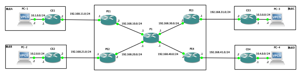
PE1、P1のグローバルルーティングテーブルには、BGPネイバー確立用の経路情報だけがインストールされ、VRF CUSTの経路情報は混在していないことが確認できます。

←MPLS動作確認 -その2

MPLS動作確認 -その2

MPLS動作確認 -その1の続きになります。

検証構成

検証構成図の再掲になります。

検証Config

PE3

!
 hostname PE3
 !
 ip cef
 no ip domain lookup
 !
 !
 ip vrf CUST
  rd 1:10
  route-target export 10:10
  route-target import 10:10
 !
 !
 !
 !
 interface Loopback0
  ip address 1.1.1.3 255.255.255.255
  ip ospf network point-to-point
 !
 interface Ethernet0/0
  ip address 192.168.30.2 255.255.255.0
  full-duplex
  mpls ip
 !
 interface Ethernet0/1
  ip vrf forwarding CUST
  ip address 192.168.31.1 255.255.255.0
  full-duplex
 !
 router ospf 10
  log-adjacency-changes
  network 1.1.1.3 0.0.0.0 area 0
  network 192.168.30.2 0.0.0.0 area 0
 !
 router bgp 65100
  no bgp default ipv4-unicast
  bgp log-neighbor-changes
  neighbor 1.1.1.1 remote-as 65100
  neighbor 1.1.1.1 update-source Loopback0
  neighbor 1.1.1.2 remote-as 65100
  neighbor 1.1.1.2 update-source Loopback0
  neighbor 1.1.1.4 remote-as 65100
  neighbor 1.1.1.4 update-source Loopback0
  !
  address-family vpnv4
   neighbor 1.1.1.1 activate
   neighbor 1.1.1.1 send-community both
   neighbor 1.1.1.2 activate
   neighbor 1.1.1.2 send-community both
   neighbor 1.1.1.4 activate
   neighbor 1.1.1.4 send-community both
  exit-address-family
  !
  address-family ipv4 vrf CUST
   redistribute static
   no synchronization
  exit-address-family
 !
 ip route vrf CUST 10.3.0.0 255.255.255.0 192.168.31.2
 !
 !
 !
 !
 mpls ldp router-id Loopback0
 !
 end

PE4

!
 hostname PE4
 !
 ip cef
 no ip domain lookup
 !
 !
 ip vrf CUST
  rd 1:10
  route-target export 10:10
  route-target import 10:10
 !
 !
 !
 !
 interface Loopback0
  ip address 1.1.1.4 255.255.255.255
  ip ospf network point-to-point
 !
 interface Ethernet0/0
  ip address 192.168.40.2 255.255.255.0
  full-duplex
  mpls ip
 !
 interface Ethernet0/1
  ip vrf forwarding CUST
  ip address 192.168.41.1 255.255.255.0
  full-duplex
 !
 router ospf 10
  log-adjacency-changes
  network 1.1.1.4 0.0.0.0 area 0
  network 192.168.40.2 0.0.0.0 area 0
 !
 router bgp 65100
  no bgp default ipv4-unicast
  bgp log-neighbor-changes
  neighbor 1.1.1.1 remote-as 65100
  neighbor 1.1.1.1 update-source Loopback0
  neighbor 1.1.1.2 remote-as 65100
  neighbor 1.1.1.2 update-source Loopback0
  neighbor 1.1.1.3 remote-as 65100
  neighbor 1.1.1.3 update-source Loopback0
  !
  address-family vpnv4
   neighbor 1.1.1.1 activate
   neighbor 1.1.1.1 send-community both
   neighbor 1.1.1.2 activate
   neighbor 1.1.1.2 send-community both
   neighbor 1.1.1.3 activate
   neighbor 1.1.1.3 send-community both
  exit-address-family
  !
  address-family ipv4 vrf CUST
   redistribute static
   no synchronization
  exit-address-family
 !
 ip route vrf CUST 10.4.0.0 255.255.255.0 192.168.41.2
 !
 !
 !
 !
 mpls ldp router-id Loopback0
 !
 end

P1

!
 hostname P1
 !
 ip cef
 no ip domain lookup
 !
 !
 !
 !
 interface Ethernet0/0
  ip address 192.168.10.1 255.255.255.0
  full-duplex
  mpls ip
 !
 interface Ethernet0/1
  ip address 192.168.20.1 255.255.255.0
  full-duplex
  mpls ip
 !
 interface Ethernet0/2
  ip address 192.168.30.1 255.255.255.0
  full-duplex
  mpls ip
 !
 interface Ethernet0/3
  ip address 192.168.40.1 255.255.255.0
  full-duplex
  mpls ip
 !
 router ospf 10
  log-adjacency-changes
  network 192.168.10.1 0.0.0.0 area 0
  network 192.168.20.1 0.0.0.0 area 0
  network 192.168.30.1 0.0.0.0 area 0
  network 192.168.40.1 0.0.0.0 area 0
 !
 !
 !
 !
 mpls ldp router-id Loopback0
 !
 end

MPLS動作確認 -その3に続きます。

MPLS動作確認 -その1

業務でMPLS網を使用したNW構築案件にアサインされましたが、「MPLSって何?」状態のため、復習も含めた動作確認検証になります。

検証目的

本検証の目的を以下に記載します。

  • MPLS網を作成すること
  • 拠点数を4とし、MPLS網に接続すること
  • 拠点を網へ接続する際は、Staticを使用すること
  • 拠点間で双方向で通信が可能なこと

検証構成

本検証における構成図を以下に記載します。

検証Config

まずは、PE1〜4のConfigからです。PEではユーザVRFとして”CUST”を設定し、仮にMPLS網に他ユーザが接続されたとしても、ユーザ間でルーティング情報が混在しないようにします。

また、各拠点間で双方向の通信を実現するために、PE間でMP-BGPによる経路交換を実施します。MP-BGPでは、Loopbackインタフェースを送信元としてBGPネイバーを確立し、各ネイバーでVPNv4プレフィックスを交換可能にするため、send-community bothを設定します。

なお、BGPネイバーを確立する際は、IP疎通性があることが前提のため、OSPFを使用しLoopbackインタフェースのセグメント情報を交換します。

ちなみに、PE側では拠点内セグメントに対し、ネクストホップをCEとしたStatic Routeを設定します。

PE1

!
 hostname PE1
 !
 ip cef
 no ip domain lookup
 !
 !
 ip vrf CUST
  rd 1:10
  route-target export 10:10
  route-target import 10:10
 !
 !
 !
 !
 interface Loopback0
  ip address 1.1.1.1 255.255.255.255
  ip ospf network point-to-point
 !
 interface Ethernet0/0
  ip address 192.168.10.2 255.255.255.0
  full-duplex
  mpls ip
 !
 interface Ethernet0/1
  ip vrf forwarding CUST
  ip address 192.168.11.1 255.255.255.0
  full-duplex
 !
 router ospf 10
  log-adjacency-changes
  network 1.1.1.1 0.0.0.0 area 0
  network 192.168.10.2 0.0.0.0 area 0
 !
 router bgp 65100
  no bgp default ipv4-unicast
  bgp log-neighbor-changes
  neighbor 1.1.1.2 remote-as 65100
  neighbor 1.1.1.2 update-source Loopback0
  neighbor 1.1.1.3 remote-as 65100
  neighbor 1.1.1.3 update-source Loopback0
  neighbor 1.1.1.4 remote-as 65100
  neighbor 1.1.1.4 update-source Loopback0
  !
  address-family vpnv4
   neighbor 1.1.1.2 activate
   neighbor 1.1.1.2 send-community both
   neighbor 1.1.1.3 activate
   neighbor 1.1.1.3 send-community both
   neighbor 1.1.1.4 activate
   neighbor 1.1.1.4 send-community both
  exit-address-family
  !
  address-family ipv4 vrf CUST
   redistribute static
   no synchronization
  exit-address-family
 !
 ip route vrf CUST 10.1.0.0 255.255.255.0 192.168.11.2
 !
 !
 mpls ldp router-id Loopback0
 !
 end

PE2

!
 hostname PE2
 !
 ip cef
 no ip domain lookup
 !
 !
 ip vrf CUST
  rd 1:10
  route-target export 10:10
  route-target import 10:10
 !
 !
 !
 !
 interface Loopback0
  ip address 1.1.1.2 255.255.255.255
  ip ospf network point-to-point
 !
 interface Ethernet0/0
  ip address 192.168.20.2 255.255.255.0
  full-duplex
  mpls ip
 !
 interface Ethernet0/1
  ip vrf forwarding CUST
  ip address 192.168.21.1 255.255.255.0
  full-duplex
 !
 router ospf 10
  log-adjacency-changes
  network 1.1.1.2 0.0.0.0 area 0
  network 192.168.20.2 0.0.0.0 area 0
 !
 router bgp 65100
  no bgp default ipv4-unicast
  bgp log-neighbor-changes
  neighbor 1.1.1.1 remote-as 65100
  neighbor 1.1.1.1 update-source Loopback0
  neighbor 1.1.1.3 remote-as 65100
  neighbor 1.1.1.3 update-source Loopback0
  neighbor 1.1.1.4 remote-as 65100
  neighbor 1.1.1.4 update-source Loopback0
  !
  address-family vpnv4
   neighbor 1.1.1.1 activate
   neighbor 1.1.1.1 send-community both
   neighbor 1.1.1.3 activate
   neighbor 1.1.1.3 send-community both
   neighbor 1.1.1.4 activate
   neighbor 1.1.1.4 send-community both
  exit-address-family
  !
  address-family ipv4 vrf CUST
   redistribute static
   no synchronization
  exit-address-family
 !
 ip route vrf CUST 10.2.0.0 255.255.255.0 192.168.21.2
 !
 !
 !
 !
 mpls ldp router-id Loopback0
 !
 end

MPLS動作確認 -その2に続きます。